Project Baja Foz!

Hey everyone, this is the new build for The Wandering Foz, continuing where the old thread left off: The Great Alaskan Tundra Humper
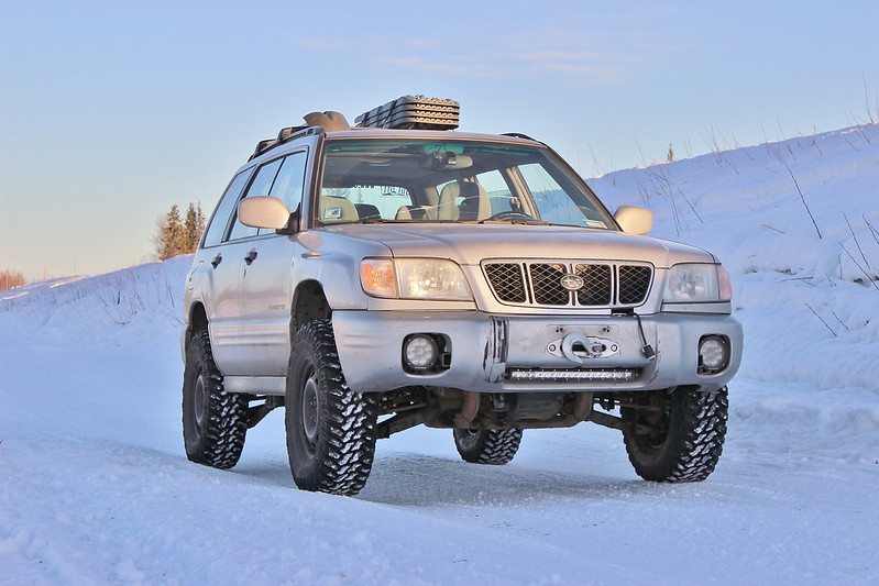
IMG_3756 by jeremiah stewart, on Flickr

Goal:
I have wanted to race the Baja 1000 since I was a little kid, but a few years ago I came across the Mexican 1000 which is a little more grassroots and easier for a normal guy like me to race in. So that's the goal! I wanted to race in their "Rally Raid AWD" class using my Hotbits coilovers as they were at the max travel for that class, but most years there is nobody in that class. Might as well try to be competitive if i'm entering a race right? So the class I'm shooting for is Score Class 7 or BITD 7200. In the Mexican 1k it'll either be "Heavy Metal Class" or "Pre-run Truck".

For now I will only be focusing on suspension so I can stay on track to be able to take the foz on a roadtrip planned for May 2017. A roll cage and a bunch of safety items will need to be built after the roadtrip unless I have the time to do the rollcage this winter. Shooting to make the race in the spring of 2018, but if the foz is ready sooner than then, then I will enter a domestic race to get my feet wet.

Plan:
  • Dual A-arm front suspension cycling 18-22" of travel
  • Dual A-arm rear suspension with toe link (will make sense later - similar to the PPI 015 Toyota) cycling 20-24" of travel
  • 32" tires on factory offset wheels to allow for longer arms and more travel while keeping it under the BITD max width of 85"
  • Either King or Fox internal bypass coilovers all around
  • High compression EG33 unless the length is more than I want to build around, then it'll be an EZ30
  • Extended length axles (+8") probably from DSS

Follow on Instagram:@thewanderingfoz
 
Thanks guys! I'm really trying to make it as good as I can without taking forever.

Update: I got my rear coilovers in last week, they're 2.5x16 Fox IBP piggy back resi's with DSC adjusters. The front's are the same, but 14" travel (and still being made):

DSC01942 by jeremiah stewart, on Flickr

DSC01946 by jeremiah stewart, on Flickr

DSC01943 by jeremiah stewart, on Flickr

It's just one thing after the other when it comes to getting things I need though, the latest of which is DOM. Hopefully later this week the shipment gets in, then like I keep saying, I'll make the trailing arms.
But I did start on mounting my cheap aluminum fuel cell (not a single damn place would ship me a good fuel cell because Alaska), i also ran all of the engine, headlight, rad fan wires, and also wired the fans to factory plugs. I also installed the master cylinder and steering column.
 
Update: I realized about a month ago that I messed up when I measured for coilovers, and the actual location of the upper mounts would be 10" above the hood, not 3" like I planned. So a few weeks ago I basically decided that I'm going to have to do a cantilever setup to be happy with the shock location; here is the current mockup:

DSC01962 by jeremiah stewart, on Flickr

The wood is where the coilover would be. There is enough room above the engine and under the hood. The motion ratio stays the same, and it doesn't add much weight, but there are two main problems:

1: The plates that the cantilevers will pivot on, as well as what the shock mount is welded to is only held to the frame rails with 2 1/2" bolts per side. It's probably strong enough, but it isn't very reassuring.

2: The shock mounts are 10" tall and would definitely apply too much torque to the plate, so it will need to be reinforced somehow, but there aren't many good places to reinforce off of.

I could also weld the plates to the frame rail so I don't have to worry about the bolts. Here are some pictures of it, note that the bent piece of 1" dom is just resting in there because I wanted to see what a gusset like that would look like:

DSC01964 by jeremiah stewart, on Flickr

DSC01970 by jeremiah stewart, on Flickr

DSC01965 by jeremiah stewart, on Flickr

All of the heims are 3/4 x 3/4 because I have a million of them.
 
Update: I got the trailing arms 90% tacked together. They are 30" long from pivot to spindle. The joints are 7/8x7/8 heims and 2" poly bushings. The crossmember is 3x3 square tubing. It's overkill, but it's simple and doesn't require any crazy tube work to strengthen it. The diff mount will weld to it, in between the inner trailing arm mounts, and the rear diff mount will just be 1.75 dom to the frame rails.

DSC01975 by jeremiah stewart, on Flickr

DSC01981 by jeremiah stewart, on Flickr

DSC01982 by jeremiah stewart, on Flickr

You can probably tell that the tubing is pretty big, but I don't want to wait another two weeks for the steel place to get their shipment. I'm using a mixture of .109" and .125" wall 1.75" and .125" 1.5" dom.

DSC01971 by jeremiah stewart, on Flickr

Full compression:

DSC01983 by jeremiah stewart, on Flickr

The track width is about 1/2" less than the front right now because I have to space the rotors out about 10mm to get the caliper in the right spot.
 
Update: I realized about a month ago that I messed up when I measured for coilovers, and the actual location of the upper mounts would be 10" above the hood, not 3" like I planned. So a few weeks ago I basically decided that I'm going to have to do a cantilever setup to be happy with the shock location; here is the current mockup:

DSC01962 by jeremiah stewart, on Flickr

The wood is where the coilover would be.

Dang, Jeremiah! That cantilever setup is crazy!

And then the trailing setup in back? Wow! You're essentially building a Dakar rally wolf in Forester sheep clothing. :biggrin:
 

Trying to think of a solution for this. The mounting plate held on by 2x 1/2" (12.5mm) bolts definitely isn't strong enough. Think of the strut knuckle using 2x 14mm bolts with a small lever (the hub) & this is effectively a 10" long lever.

You will need to create a bracket running to the strut towers & I suggest also towards the front of the guard. That part isn't very strong but at least it will provide triangulation.

The other option is to run short shocks mounted in the middle above the engine towards the firewall. I see you have the cantilever arm connected to the middle of the upper A arm. This will halve the motion of the coilovers meaning you can use a coilover that is half the length but with the same suspension travel. If you do this you will need to move the cantilever system so it's all in line with the direction of force in the coilovers
 
I do not have the knowledge to participate much but I wonder about tire sizes.

Isn't 35" more of a handicap than an advantage, considering the available power, low gear reduction, and so on?
 
Trying to think of a solution for this. The mounting plate held on by 2x 1/2" (12.5mm) bolts definitely isn't strong enough. Think of the strut knuckle using 2x 14mm bolts with a small lever (the hub) & this is effectively a 10" long lever.

You will need to create a bracket running to the strut towers & I suggest also towards the front of the guard. That part isn't very strong but at least it will provide triangulation.

The other option is to run short shocks mounted in the middle above the engine towards the firewall. I see you have the cantilever arm connected to the middle of the upper A arm. This will halve the motion of the coilovers meaning you can use a coilover that is half the length but with the same suspension travel. If you do this you will need to move the cantilever system so it's all in line with the direction of force in the coilovers

I think we are thinking about the same solution? Here is my idea (note the two tubes):

DSC01962.2 by jeremiah stewart, on Flickr

That would keep the shock mount from applying leverage on the base plate, and as for the amount of force upwards on the cantilever which would apply a tension on the bolts, we're talking about maybe 2000lb force upward (currently doing the real math to get this totally figured out). The tensile strength of a grade 8 1/2" bolt is about 17000lb force (depending on who you get your info from), and the plates have two of them, so we have 34000lb force of tensile strength there.

The reason I don't want to mount a short shock half way on the control arm is because that motion ratio would require very aggressive valving (making more heat) along with much less available surface area of shock body as well as less fluid volume, and therefore less heat capacity and dissipation. Plus it is a lot more stress on the control arms.

I don't want to sound like i'm just being defensive or argumentative, just sharing my thoughts here, let me know what you think!

I do not have the knowledge to participate much but I wonder about tire sizes.

Isn't 35" more of a handicap than an advantage, considering the available power, low gear reduction, and so on?

Yeah, 35" tires are just my goal, but I will wait for a drivetrain with better ratios before doing that. For now I'll have to stick with my 30's though, then try 33's as soon as I can.
 
Have you considered 255/85r16 as a tyre size? Nice and skinny, so would work well with a lightweight Sub. Comes out to 33.1x10.1r16.
 
Have you considered 255/85r16 as a tyre size? Nice and skinny, so would work well with a lightweight Sub. Comes out to 33.1x10.1r16.

I wanted to but R16 tires of that diameter range are all so heavy because they are a load range E usually. The 33x10.5r15 I want to run are load range C. The other nice thing about 15 inch wheels are that a lot of tire companies make race only (non dot) tires for them that are super light which could be beneficial later.
 
Last edited:
Also tie the 2 posts together. Basically, the more reinforcing you can have to the cantilever posts the better. Don't think about it in terms of a slow steady push, imagine it bending rapidly back & forth like bending a thin piece of metal in you hands back & forth until it snaps. Metal fatigue is the enemy here
 
Tying them together was my original plan because it helps the most for the least amount of tubing, but I have to wait and see if I have enough room for a tube to fit under and in between the coilovers. Also, we did some math (my friend did most) and figured out that the bending force on the 1/2" bolt that supports the two heims for the cantilever will only undergo less than 50,000psi of bending force (grade 8 can withstand 150,000psi minimum). But that's not taking into consideration the damping Force applied by the shock, and it's complimentary force applied by the wheel. The calculations are based on full static loading at all angles of the cantilever's range, with both forces applied. So for now we're looking safe in that regard. Might end up just having to huck it with no hood or fenders to test it, incase the cantilever gets launched out of the engine bay lol.
 
I wanted to but R16 tires of that diameter range are all so heavy because they are a load range E usually. The 33x10.5r15 I want to run are load range C. The other nice thing about 15 inch wheels are that a lot of tire companies make race only (non dot) tires for them that are super light which could be beneficial later.

That's true, hadn't considered load rating.
 
Update: This is what I was thinking for the rear shock mounts:

DSC02011 by jeremiah stewart, on Flickr

It's 1.75 DOM mounted via 2 1/2" bolts sandwiching the rear sheet metal (multiple layers about 1/8" thick total) with a backing plate, and mounted to the C-pillar seat belt holes with the factory M13 bolts (3 per side). The bar spanning the width of the car is just for added C-pillar support.

DSC02012 by jeremiah stewart, on Flickr

DSC02015 by jeremiah stewart, on Flickr

I'm thinking about adding a gusset of some sort to the top of the shock hoop, and then rotating the lower shock mount so there is no misalignment through it's stroke. What do you guys think? I figure the worst that could happen is the shocks go shooting through the roof or out the windows lol.
 
Good to see the rear wheel arches are not taking any stress as they are prone to cracking the spot welds.

Are you building a wardrobe in there as well - kool! :lol:
 
Jeremiah, if you're still looking for front CV axles, the Subaru SVX's 3.3 will be perfect for you ! Inner CV's are plug and play on the male EJ gearbox, are much larger and take more than 30° angle. Outer CV's are larger too and will fit if you change the dust seal for a thinner one, or you can swap the outer SVX CV for a standard Forester, Legacy, Impreza one.

My next upgrade, already have one and am looking for another one at the wreckers !
 
Well as hard as I tried, I did not have the Forester done in time for the road trip due to having to move out sooner than was really managable. But last Tuesday, we pulled an all-nighter to put the entire suspension, brake system, interior back together so that I could take to a driveshaft shop and a shop to get the front wheel bearings done. This was how high we had to jack it up in the garage to get the 30's on:

DSC02146 jpeg by jeremiah stewart, on Flickr

It ran like garbage all the way to work Wednesday morning; cutting out, hunting for idle, dying at stops. The annoying thing was that the only way to get the driveshaft done in time was to spend my lunch break installing the rear diff and removing the driveshaft to take it to the place with measurements, and furthermore, to also uninstall the knuckles to get new wheel bearings pressed in. I ended up leaving the Forester at work until Friday night, spending the last few days to get all moved out of the apartment. Oh, I guess on Thursday night is when I tried to drive it back home to fill it with junk to store for the summer because I had a new plan for the roadtrip. But not even half way home, the fuel pump died. This made sense considering the odd runability with no codes. So it was already midnight at that point, and we had to drive over to the next town of North Pole to get a fuel pump from a friend. With that installed, I fired it up and it ran like a champ but the serpentine belt was screeching like a mofo because it was brand new and stretched a bit. I killed the engine, tightened the belt, and then it wouldn't start! It had a code for the IACV, so we went home, took the one off of my Impreza, drove back and swapped it onto the Forester with no luck; same issue, same code. It was 3am at this point and I was defeated. We pushed it into the trees off the road and left it. Friday night after my last day of work, we towed it with a strap to a friends house where it will sit all summer.

This is what it looks like currently:

DSC02156 jpeg by jeremiah stewart, on Flickr

Although this whole ordeal really made me want to give up entirely, I'll be back in the fall to do something with it. At this point I definitely don't see myself making it to the Mex 1k next April lol.
 
wow - what an amazing beast you've made.

I can't see how a couple of trifling engine gremlins could stop you !
 
I know you're feeling down but don't give up, you'll get there. You're doing a complete ground up build of a new design (not a rebuild) so there will be many setbacks. Just work through each one, one at a time, & you'll get it done

Looking great so far! :monkeydance:
 
Amazing things never come about without pain.
 
Back
Top