Project Baja Foz!

Hey everyone, this is the new build for The Wandering Foz, continuing where the old thread left off: The Great Alaskan Tundra Humper
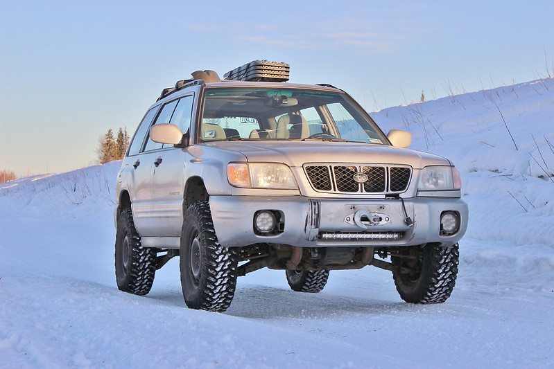
IMG_3756 by jeremiah stewart, on Flickr

Goal:
I have wanted to race the Baja 1000 since I was a little kid, but a few years ago I came across the Mexican 1000 which is a little more grassroots and easier for a normal guy like me to race in. So that's the goal! I wanted to race in their "Rally Raid AWD" class using my Hotbits coilovers as they were at the max travel for that class, but most years there is nobody in that class. Might as well try to be competitive if i'm entering a race right? So the class I'm shooting for is Score Class 7 or BITD 7200. In the Mexican 1k it'll either be "Heavy Metal Class" or "Pre-run Truck".

For now I will only be focusing on suspension so I can stay on track to be able to take the foz on a roadtrip planned for May 2017. A roll cage and a bunch of safety items will need to be built after the roadtrip unless I have the time to do the rollcage this winter. Shooting to make the race in the spring of 2018, but if the foz is ready sooner than then, then I will enter a domestic race to get my feet wet.

Plan:
  • Dual A-arm front suspension cycling 18-22" of travel
  • Dual A-arm rear suspension with toe link (will make sense later - similar to the PPI 015 Toyota) cycling 20-24" of travel
  • 32" tires on factory offset wheels to allow for longer arms and more travel while keeping it under the BITD max width of 85"
  • Either King or Fox internal bypass coilovers all around
  • High compression EG33 unless the length is more than I want to build around, then it'll be an EZ30
  • Extended length axles (+8") probably from DSS

Follow on Instagram:@thewanderingfoz
 
you are not considering a manual dualrange?

I am not because it would cost a ton to build a dual range tranny that can handle the torque. It's much cheaper to make an auto survive baja than a manual. Just have to keep the auto cool. I think my dream tranny would be dual range, dccd 6 speed with ppg gears and dog engagement haha.

Do you keep the oem MPT 4EAT or do you upgrade to the VTD ?

Was planning on keeping it, but never looked at VTD. I have never felt let down by the MPT though. I'd be a little scared of rear diff temperatures running the VTD with an r160 and 30+ inch tires. What do you think?

Awesome, you really are pushing the boundaries! :monkeydance:

I'd be happy to make a couple of suggestions if you like...

Please do! Don't hesitate to throw your two cents in!
 
Was planning on keeping it, but never looked at VTD. I have never felt let down by the MPT though. I'd be a little scared of rear diff temperatures running the VTD with an r160 and 30+ inch tires. What do you think?

The VTD is an excellent auto and might be needed to handle the extra power. Have you done the centre diff lock mod yet?

Please do! Don't hesitate to throw your two cents in!

Just a couple of suggestions. The engine crossmember will receive a huge amount of force, not just in a lateral direction but also twisting, from the suspension. The longer suspension arms will multiply the force. I would vastly over engineer it so it can handle hitting a large bump at speed. I think the 2 sides need to be joined along the full length at least along the back if not fully boxed.

The LCA rear bush spacer looks very nice but doesnt have enough meat on the side pieces. I would do a solid piece without the cutouts. The weight saving is less than a cup of coffee lol.

I believe in over engineering anything that receives a lot of force & I'm sure when you're finished the build you'll be dong some awesome "adventurous" trips lol
 
The VTD is an excellent auto and might be needed to handle the extra power. Have you done the centre diff lock mod yet?

Just a couple of suggestions. The engine crossmember will receive a huge amount of force, not just in a lateral direction but also twisting, from the suspension. The longer suspension arms will multiply the force. I would vastly over engineer it so it can handle hitting a large bump at speed. I think the 2 sides need to be joined along the full length at least along the back if not fully boxed.

The LCA rear bush spacer looks very nice but doesnt have enough meat on the side pieces. I would do a solid piece without the cutouts. The weight saving is less than a cup of coffee lol.

I believe in over engineering anything that receives a lot of force & I'm sure when you're finished the build you'll be dong some awesome "adventurous" trips lol

Thanks for your suggestions! I had done the diff lock mod to my old forester, and still have the resistor pack i made, but I never put it in this forester because It has done an impeccable job at locking up when needed. I hardly used the switch in my old forester because it made little difference unless I was on ice. The VTD I will look further into..

I agree with you on the upper A-arm mounts, and what you have suggested is actually what I had planned, and even had back pieces tacked on for a while. But i think you may be happy to see what I have decided to go with for the upper mounts instead of using those bits. I'll post pics tonight after I have it tacked together.

I do agree with you about the rear bushing mount as well; I was having fun with CAD just making the design, I wasn't shooting for weight savings haha. I think when you see how I'm planning on using it, you'll agree that it's going to be totally fine.
 
Yeah I'm sure you'll be doing lots of design alterations as you progress with the build. looking forward to seeing how you go :)
 
Would've thought a standard 4EAT from a JDM Legacy GTB (Gen3) or GT (Gen4) or similar would be a good starting point. They dealt with 280hp (turbo) or 250hp (3.0L) out of the box.

USDM got the 2.5L Gen4 turbo in Auto -- too easy.

Gen3 certainly had a 'sport shift' mode that supported full manual operation, so I'd be surprised if you needed to change control systems.
 
Alright I did a little bit this weekend after making the most of the warm weather. First I cut up the subframe tremendously and bent a tube:

DSC01001 by jeremiah stewart, on Flickr

Tacked on some tabs:

DSC01003 by jeremiah stewart, on Flickr

A little mockup to ensure full droop would be obtainable without the upper heims hitting the tube they are on:

DSC01002 by jeremiah stewart, on Flickr

I then began to bend the piece of tubing that will go around the back of the transmission so that i could get the mounts figured out, but apparently when they say "up to .095 DOM" can be bent with this bender, they weren't lying. I need to get a new bottle jack now:

DSC01010 by jeremiah stewart, on Flickr

The shaft is so bent that I can't retract it at all, so the tubing is stuck under tension. I left it for tomorrow. The plan now is to either get rid of the remaining laser cut subframe pieces and replace with DOM, or box it in and reinforce it with a small amount of DOM since it's only holding the engine and rack.
 
I made some awesome progress today! I managed to get a good start on the arms:

DSC01020 by jeremiah stewart, on Flickr

DSC01021 by jeremiah stewart, on Flickr

I initially had 15.5" of travel, but after moving the upper mounts out about .5" I now have 19"!!! I think I may strap it at 18" because the upper arm would be under a lot of force when drooped far enough for 19":

20170203_184038 by jeremiah stewart, on Flickr

20170203_184100 by jeremiah stewart, on Flickr

You can see up there what the final shape of the upper arm is. I'll gusset the triangle where the uniball is and that's where the shock will mount.
Here are some shots looking at full bump:
With fender:

DSC01031 by jeremiah stewart, on Flickr

Fender removed showing a couple inches un touched to the chassis:

DSC01032 by jeremiah stewart, on Flickr

And with the tire (30" dia.) touching:

DSC01033 by jeremiah stewart, on Flickr

But the upper arm still has a lot of clearance:

DSC01039 by jeremiah stewart, on Flickr

So I'll be needing to make about 3 inches of tire clearance up top.
Finally, using a level app I have determined that the caster is right where I wanted it, at 7 degrees. The camber at ride height is showing 4 degrees, but that can be adjusted out. The CV angles are golden, and ultimately I am very happy with this.
 
What are your cv axles ?

Will you go double wishbone rear too ?
 
Thanks guys, Jf1sf5, your CV question is answered below.

I picked up some thin wall 1.25 tubing for the lower control arms, but I'm still waiting on a replacement jack for my bender so i can build the driver's side control arms. I did get the tie rod setup mocked up:

DSC01257 by jeremiah stewart, on Flickr

It's a 3/16" thick clevis bolted to the rack with a class 12.9 M14 bolt, the heim spacer is there for mockup, and puts the joint inline with the upper and lower control arm mounts. There is a tiny amount of bump steer that seems to occur at full droop and bump, so I think I need to space that clevis out just a touch to shorten the tie rod, but we're talking like 1 or 2 degrees of toe change.

I also began talking to axle companies about some custom axles, Drive Shaft Shop wasn't very helpful or friendly and they quoted me about $1200 per axle. CVO (Constant Velocity of Ocala) quoted me $500 each. I'm not going to ask RCV because that's just obviously out of my price range. So for now, I'm going to see how it goes with CVO, they said that max plunge on their inner CV's are .75" (same as DSS) and you may recall me saying I had 1.1" of plunge, well that became 1.68" and now i have it down to a solid .875" and can't get it any lower without reducing travel. So since the plunge is equal at a depth of .875" at full bump and droop, I think for now I'll limit travel to 17" since most of the plunge is within those last few inches either direction. Then later in the future I'll run an RCV 930 cv that has over an inch of plunge with SubaruGears 930 flanges.

Lastly, after taking some more measurements of the rear end, I've figured out that there's not enough room to fit 24" of travel with dual A-arms back there because the frame rails are so low and far apart. So I think I am going to do a trailing arm setup like class 1 cars. I ran some numbers and measured, and it looks like 24" of travel is doable within the space provided and with not a whole lot of axle plunge due to the axles being so long. I wasn't able to account for setting up the axles at an angle at ride height which reduces plunge further, but i'm confident I can at least get 22" with those same 930cv's. The only drawback that I see with the trailing arm setup is that there is no camber change in the cycle, but having driven a Can-am commander quite a bit, and with the old suspension setup on the forester having almost no camber change from ride height to full compression, I can't say it'd bother me. I have no issues with it, and to me it beats having a semi trailing arm setup as well as a weird trailing A-arm setup. Plus i think trailing arms look badass.
Let me know your guys' thoughts.
 
I finally 100% completed something!

DSC01299 by jeremiah stewart, on Flickr

DSC01298 by jeremiah stewart, on Flickr

DSC01297 by jeremiah stewart, on Flickr

The new engine mounts put the engine 1" lower than with the stock mounts, which got my cv plunge down to 7/8" and I went with polyurethane instead of moving the mount down because I don't want to run the risk of a cv bottoming out in the cup due to engine movement.
I also got the driver's side control arms started:

DSC01335 by jeremiah stewart, on Flickr

And here is what i was talking about for the rear subframe mount:

DSC01334 by jeremiah stewart, on Flickr

Here are some fun to look at pictures showing most of the travel. The jack doesn't go high enough or low enough to get it all, and keep in mind the rear is on jack stands and the tires are 30x9.5r15's but actual diameter is only like 29.3" new:

Ride height:
DSC01302 by jeremiah stewart, on Flickr

Almost full droop:
DSC01304 by jeremiah stewart, on Flickr

Almost full compression:
DSC01306 by jeremiah stewart, on Flickr

Clearly if I nose it into the ground it won't be a great day. But that's what i get for choosing an H6 that sticks out front super far.

DSC01307 by jeremiah stewart, on Flickr

That's it for now, but I've got a lot of goodies on order so stay tuned.
 
Thanks guys, i'm super happy about how nicely it's coming along. It keeps the enthusiasm up!

Coffee break update:
Lower control arm reinforcements are tacked in both sides, and I am loving the symmetry!

DSC01343 by jeremiah stewart, on Flickr

Also, using the last bit of 1/8th wall tubing I had, I made the rear portion of the subframe which will hold the tranny. It's not done yet but the basics are there. I realize now that I can't drop the transmission with this setup, but I'll get tube clamps to make the rear horizontal bar removable:

DSC01341 by jeremiah stewart, on Flickr

So now I just need to put some more reinforcement pieces in the subframe and It'll almost be ready to be fully welded.
 
Nice progress Jeremiah !

Any news from CVO for your custom axles ? Wouldn't oem axles with longer shafts work thanks to the wider stance ?

Bon courage !
 
Good, I didnt want to say anything until I saw how you were doing that. Looks good mate!

Thanks man! Are you talking about the lower control arms or rear part of the subframe?

Nice progress Jeremiah !

Any news from CVO for your custom axles ? Wouldn't oem axles with longer shafts work thanks to the wider stance ?

Bon courage !

OEM axles with longer bars would work, but since I'm running that high comp H6 and had problems with inner joints disliking whoops with the old setup, I figured I should go big..

That leads me to this small update; I got some 930cv flanges from Australia!

DSC01350 by jeremiah stewart, on Flickr

DSC01351 by jeremiah stewart, on Flickr

It's insane how fast I got them, they shipped out on Monday. Now that I have them, I can give CVO the measurements and get axles made. Then for the rear end I think i'm going to get Subarugears other flange for the R160 which adapts it to a 100mm type 2 CV.

For the rear trailing arms, I am going to be using a 5x100 unitized hub and I was thinking that i should go with a front hub from an outback since they are stronger than the rears, then run a Forester front disk with the 2 pot calipers and run WRX 4pots up front. I'll convert it to a hydro parking brake too. Then later when i make custom front knuckles, I'll use the same hub so that I can just carry one spare. Also, it'll allow me to run a larger cv on the outer in the rear, which with the type 2 inner CV will be nice and strong (ready for that cap locker!).

What do you guys think about that plan?
 
Last edited:
I think that its just another booooring Forester build :biggrin:

Na, its just insane :lildevil:

Did you get the 930cv flanges from Subarugears ?
 
Back
Top