Accessory plug consant 12V power - incl a walkthru

It's very easy even for a novice like me, it took about 15 mins all up including soldering the "add-a-fuse" and reading the book to work out which fuse powers the outlets.
 
Spoke too soon, the add a fuse is starting to cause havoc with my relays, the AC relay keeps kicking off if the add a fuse isnt pushed in on a specific angle, im doing the relay jump method now, will do a writeup for outback owners.
Did a writeup, perhaps sticky that and remove this? I would not recommend using the add a fuse anymore it was proving to be too much of a load on the fuses and cutting the relays somehow.
 
Last edited:
Walkthrough: Making cargo area 12v outlet constantly on

This is a guide for making ONLY the rear cargo area 12v outlet constantly on. Works on Outbacks/Foresters
Experience Needed: None (I did it:raz:)

Tools Required:
Screwdriver
Wire Strippers/Crimpers
Electrical Tape
10 centimetres of 2.5mm or equivelant electrical wire.
2 male spade electrical terminals.

Steps:
The idea of this mod is to remove the relay that controls the power received to the rear 12v outlet, and wire a bridge onto its wiring plug that allows the wiring to be on all the time. The relay that controls the power to the plug is located on the side of the kickpanel fusebox near where your feet normally are.

Step 1:
Remove the lower trim below the steering wheel, on my car (2000 Outback) this is achieved by using a screwdriver on this bolt in the corner of the trim:
60ecd899.jpg

And these 2 plugs on the side are unscrewed and pulled out, after this the trim unclips and slides off.
ffb013d3.jpg

It will reveal this underneath:

632446ce-1.jpg

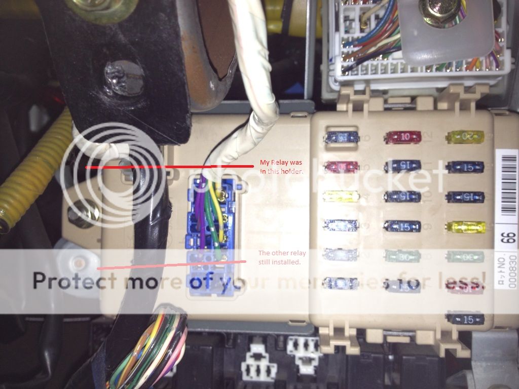
You can see on the side of the box there is space for 2 relays. The relays are removed by unclipping the white clip that holds them in their holder.
In this photo i have removed the relay that controls the power to the rear outlet on my model and highlighted it, it may be different on your model of car, the easiest way to tell if you have the right one is to unplug it and turn your car on and see if the outlet in the back works or not.

Step 2:
Once you have figured out which relay it is, unplug it, it is not longer required, you may feed it to your enemies if need be, but first on the side of the relay itself it has its wiring diagram, it uses numbers to tell you what pin does what on the circuit, for my car the pins that need bridging the provide constant power are 3 and 4, this is the same for foresters aswell, when you look under the relay at the 4 pins coming off it it is the 2 COPPER coloured pins that need bridging. Simply line the relay up with the plug it was plugged into, work out which holes on the PLUG the COPPER pins on the relay plugged into and remember them.

Step 3:
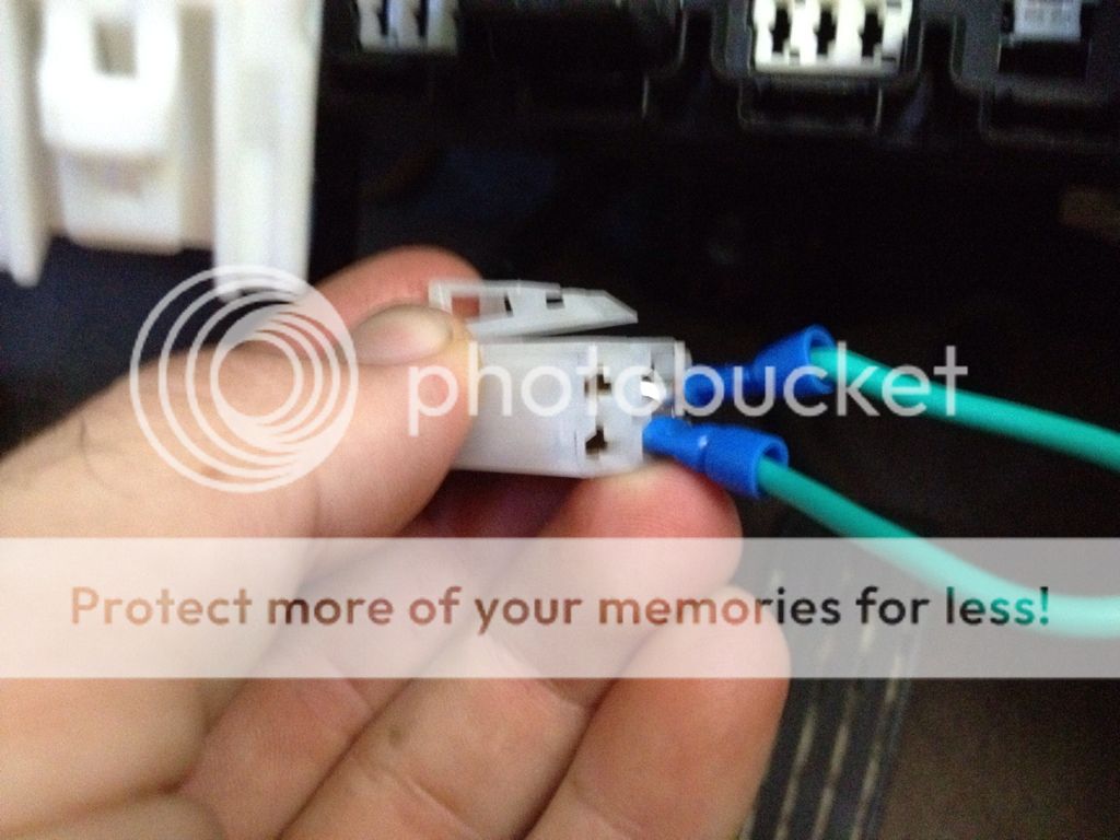
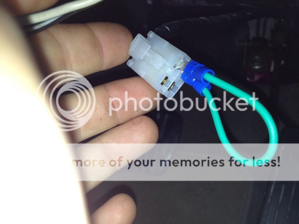
Using the length of electrical wire and the 2 male spade connectors make a bridge using the wire crimmper to use in the plug that was plugged into the relay.

Step 4:
Insert the bridge into the holes on the plug that corresponded with 3 and 4 on the relay.
Heres what mine looks like:
2099313a.jpg

2efb3c3b.jpg

Step 5:
Test that the outlet is working without the ignition on, electrical tape the connection up and reassemble your trim, your done!
 
Great idea to write this up & thanks for making it a sticky so its easy to find :biggrin:

I wanted to add a hard-wired accessories point in the front while keeping the cig lighter ignition-switched & at the same time making the rear accessories point always on. So I did the (easy) mod described below but added an extra power wire (in blue) routed behind the dash. A couple of pop rivets to hold the accessories point in place on the side of the centre console & an earth up behind the dash & I was done :monkeydance:

Installed (always on):
img2449hl.jpg


Relay bypass plus extra power wire:
img2454yt.jpg


The only prob I had was when I put the wire in the connector the free end of the bypass loop momentarily touched the metal frame, blowing the fuse. Solution...put in the free end first, then the power end.
 
Gidday Taza & All

I want to make all my 12V sockets live all the time.

I also want to install a multi-outlet + USB charger in the dash top bin. I have tried to get the clock trim off, but got to a point where I thought something was going to break ...

So I could do with a bit of advice ... :poke: :iconwink:. TIA.
 
Ratbag, can you take a photo and then I can give you an idea how to get it off. It's different to the SF and I don't have one to look at...
I now have most of my constantly live sockets running from my 2nd battery. That way I know I won't drain my main battery...
It's pretty simple to make the main ones constant, AS we do it at work though we run new wiring that's a thicker gauge to the outlet as the stock wiring can burn out pretty easily.. I wouldn't of done what Nachaluva did with the relay but that way does work..
 
I wouldn't of done what Nachaluva did with the relay but that way does work..

I'm just a lowly hack, not a proper sparky lol :raspberry:

Running heavy gauge wires direct from the battery through a 30A fuse would be best, but this was easy & all I need...at least till you come over & rewire my Foz lol :rotfl:

Speaking of rewiring...when you do your EJ25, you should do a thread incl mating the engines wiring loom to the cars loom... :poke:
 
Gidday Taza

Ratbag, can you take a photo and then I can give you an idea how to get it off. It's different to the SF and I don't have one to look at...

Thanks, mate. Will have to be in a couple of days. I have hurt my back. Don't even know how ... :(

I now have most of my constantly live sockets running from my 2nd battery. That way I know I won't drain my main battery...
It's pretty simple to make the main ones constant, AS we do it at work though we run new wiring that's a thicker gauge to the outlet as the stock wiring can burn out pretty easily.. I wouldn't of done what Nachaluva did with the relay but that way does work..

I am always very wary about the total drain. Amperage can easily go through the roof at 12V.

Eventually, I want to mount my second battery in my trailer. Not to be used for starting (unless I remove it and use jumper leads), just for appliances, lights etc.

I may have to run a secondary trailer hook-up wire set to provide for charging from the car. Either that, or use the unused pins in the standard trailer connector. They should be good for the 5 amps or so needed for trickle charging. Don't think that the vehicle wiring loom that the trailer connector uses would be though.

Basically, I don't want the auxiliary battery in the car.
 
Thanks for that link, SJ.

Looks promising, if one only glances very quickly at the price ... :(
 
Gidday Folks

I know that this thread has antique value ... :iconwink: :lol:, but I want to do something slightly different.

What I want to achieve is to still have the three power outlets powered on when the ignition is fully off, but I want this to be manually switchable so that I can leave either or both circuits on for minor stops, but switch them off when stopped for longer periods.

What I am proposing to do is to add a couple of standard illuminated switches either in the switch block to the right of the ignition switch, or in the two blank positions just under the centre front armrest in my SG Forester. I realise that the second position would require running some wiring from the current position of the relays to the switches and back, but that's not hard to get at in either position for the switches.

Firstly, I would have to perform the minor surgery above, with the difference being that there would now be a switch inserted between the two fixed wiring connections that are being bridged by the jumper in Wombat's write-up above.

The dash cigarette lighter circuit is fused at 15A. This circuit should have plenty of amperage to run GPS, Spot Messenger, phone, laptop car charger(6A @ 12V + and auxiliary 2A USB power port - I intend to run a 2A powered USB hub off this, and plug all the above items into that hub).

Is the second relay pictured controlling the 20A circuit to the cargo area and centre console accessory outlets? Can it be similarly wired as constant on, but manually switched?

The 20A circuit for these two outlets will have my backup battery/power supply plugged into it (about 2-3A total draw) and my fridge when moving (about 6.25A draw).

According to the Owner's Manual, fuse box positions 22 and 23 are not used. Fuse 22 is a 15A circuit for heated seats (not fitted in my car!), and Fuse 23 is listed as "empty". I haven't looked to check if there is power available to either or both of these two circuits.

I also need to find a circuit to power my Oricom UHF in-car CB. It is fused at 2A draw. Perhaps I can use either fuse 22 or 23 for power for this unit?

Any thoughts?

[EDIT]

The above is all well and good in theory. On checking the actual internal fuse box in my car, fuse positions 20, 21, 22 and 23 do not appear to exist.

There is a sort of plug where they are supposed to be located ...

FALSE ALARM: When I grovelled in the foot well, there is a little label that says these fuses are located alongside the relays on either side of the main fuse block ...

[end edit]
 
Last edited:
ive done a perminant live to my battery, fused of course lol
I use it just for a solar charger when the car is going to be parked up for a while, works a treat :)
 
I also need to connect the two wires in my trailer hitch that are tied back at the connection to the car's wiring loom end.

Guess that I'll have to look up the standard wiring diagrams for a 7 pin large round, and a 7 pin flat to find out which one of the unused terminals is for reversing lights, and which is for 12V. Then connect up the appropriate wires to whatever I can find around that are inside the car.
 
Back
Top