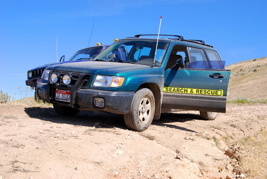
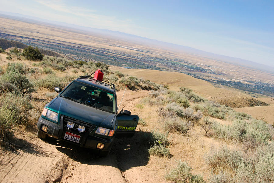
Forester SAR Concept, Front Bullbar/Rear Bar

TrooperBrian

Forum Member
Joined
Jan 30, 2011
Messages
26
Hey everyone, just found this forum from the guys over at SubaruForester.org, thought I would share my rig these days.

The front bar details:

Full Thickness 5/16" Hotroll Plate
2.5" OD Main Bar
2" OD Top Bar
Grade 8 Steel Bolts, all mounting points.
Grade 5 Steel Nylon Locknuts, all bolt points.
Twin 130w Offroad Lamps w/ 30A Relay, wired to Siren Controller

Full bends and fab by hand, no heavy equipment or oxy-acetylene fuel rosebud torch. (why it took so long)

Oh and thanks to the guys at TSP for always getting me the right parts, and the guys over at Pacific Steel for getting me good deals!
Best_Shot_by_GlockGuy.jpg


Progress_by_GlockGuy.jpg


Eventually I added parts to the rear bar including a hitch assembly and some tiedown loops.

Also a 2" lift all around.

Starting with 4" Sch10 pipe, runs about 4.3"ID, which is the perfect size for the front strut cap.

dsc4413medium.jpg


A bit of math:

dsc4428medium.jpg


Removing 1.57" from the circumference of the pipe gives an overall reduction in pipe radius of about .25", and a reduction of .5" to about 3.7"ID, which is the right size for the rear struts.

Just cut out the notch, weld it back together, then true the radius.

The front was about as hard as the rear. But the bushing bolts could be directly pressed out.

dsc4410medium.jpg


Here's the strut out.

dsc4415medium.jpg


How I designed my lift:

dsc4417medium.jpg


For an extended strut bushing, I used 30mm M8x1.25 A2 Stainless bolts, with G8 nuts.

dsc4423medium.jpg


The rear was a bit harder. For one it was hard to place jackstands where the car wouldn't tip over with excessive prying force. The rear sway bar also had to come off (like a tutorial I read) in order to facilitate enough clearance to get it back in.

dsc4424medium.jpg


Here is the rear spacers done:

dsc4425medium.jpg


Here is the front lifts in, compared to a stock height in the back.

dsc4422copymedium.jpg


And here is the rear done with the tire on the ground.


On top of that, the brake lines had to be disconnected front and rear, and the ABS sensor on the front wheels. Then the brakes bled and reinstalled.


dsc6136copymedium.jpg


dsc6133copymedium.jpg


dsc6138copymedium.jpg


I just found this picture from a few years ago, I don't think I ever posted it. :D

94201124094659178113145.jpg
 
Nice. Looks great.

I love the DIY lift kit. Also the front bar looks excellent. Do you have a tutorial or instructions on how you did the front bar? along with any pics? I would love to put one together like that for my foz. Also how did you attach the front bar to the under front side of your foz aswell?

Regards
Taza
I had them on a server, but it was decommissioned earlier this year. I'll try and find them again and reupload.
 
^ Damn. Ok thanks. My home server is down but the 5tb sitting in it are not lost. thank god.
I would love to try and put one together like that. Only problem is it may not be legal in Australia.
 
Well I had a look around the archives, I didn't really take any progress pictures it looks like. I think I was too busy swearing in a 120 degree shop wearing a full jumpsuit and using dirty power.

But what you see on the front bar, including the mounting assembly came from these two pieces of steel:

dsc0867medium.jpg


And this plate of hot rolled steel where I took cardboard cutouts and traced them:

dsc0868medium.jpg


Resulting in:

dsc0872medium.jpg


This I eventually took out to an offsite shop and plasma cut. Then it was about another three hours with a grinder to smooth out the edges.

a_very_quiet_range_day_by_glockguy-d35e6gv.jpg


I bored three holes to mount the actual bar (for replaceability) to the substructure. But cutting the steel had tempered slightly, and I burned through 4 1/2" TiNi drill bits before giving in to a 10% cobalt bit and bored through it.
 
Howdy and :welcome:TrooperBrian!!!

Very nice looking Foz!!! And a working one too.:cool:
Question did you build any camber correcting offset into your lift??? And if so, how much???
 
Aaaaah ok I used a different camera, so it was in a different folder.

So I cut a slit and bent a hole into the flat bar so it could be bent without a press:

cimg4949medium.jpg


Then fillit welded that area back in and ground it down. Repeat for both sides.

cimg4950medium.jpg


The completed substructure:

cimg4948large.jpg


It mounts where the original tie down points were. With this design there is no decrease in approach angle and I've been able to push a few logs and yank out other cars with no issues.

An underneath view:

cimg4957medium.jpg


Here is bending the flat bar around and welding manually, which required three adults and some very long poles:

cimg4951large.jpg


The completed front bar:

cimg4961medium.jpg


Nyloc nuts and G8 bolts from TSP:

cimg4958medium.jpg


Also electrical work done in house:

cimg4960medium.jpg


cimg4959medium.jpg


What it looked like starting out:

cimg4928medium.jpg


Eventually not being able to bore through the steel, I cut the piece off and welded on a new one. Less hot this time.

cimg4943medium.jpg


cimg4944medium.jpg
 
Howdy and :welcome:TrooperBrian!!!

Very nice looking Foz!!! And a working one too.:cool:
Question did you build any camber correcting offset into your lift??? And if so, how much???
Thanks. :D

No correction was built into the lift, I determined it to be more stable this way, and much easier to install. Also less welds and plates required.

Actual offset runout was approximately 1.8 degrees positive on all four tires. I then went back in with 3deg camber correction bolts to fix this. Alignment was returned to factory spec.

That's good to know you were able to do it only using camber bolts. Did you use a lower plate at all, or does the open end of the pipe just sit on the strut top?

Actually if you have pics and info, if you have the time sometime would love to see it posted up in the DIY Lift Thread.:)
 
...

a_very_quiet_range_day_by_glockguy-d35e6gv.jpg


I bored three holes to mount the actual bar (for replaceability) to the substructure. ... I burned through 4 1/2" TiNi drill bits before giving in to a 10% cobalt bit and bored through it.

So, cobalt tipped rounds? Look a bit less than 1/2" to me! :twisted:
 
G'day TrooperBrian & :welcome: to ORS.

I must say that a nice Forry you have there mate. :)

Well done with the DIY lift & the other mods too mate, very well done indeed. :ebiggrin:

Regards
Mr Turbo
 
In the coming months I'll be putting together an aluminum sump guard, and some brush guards. Modular design so if I bend or break any parts I can change them with a few bolts without removing the entire bar.

Also some recovery points, lift points, and an overhead light bar. :D
 
In the coming months I'll be putting together an aluminum sump guard, and some brush guards. Modular design so if I bend or break any parts I can change them with a few bolts without removing the entire bar.

Also some recovery points, lift points, and an overhead light bar. :D

Hey Brian, any updates on that? I'm interested to see what you've done as your bullbar is awesome.

Plus, well, it's so awesome I want to build one too! Most of it is easy enough to figure out with your pics, but... I'm not sure I understand how it's mounted. Did you remove the bolded-on tow hooks and bolted the bullbar there? Is it fixed anywhere else on the frame, or just there? Some closeups from how it's mounted would definitely help :)

EDIT: Actually re-reading the original post. this seems to answer the question:
Only point I'm still unsure... I understand you removed the tow hooks and just bolted them instead? Then do you have pics of how you mounted the tow hooks to the bar? (since those in your thread here: https://offroadsubarus.com/showthread.php?t=2525 don't show up)

It mounts where the original tie down points were. With this design there is no decrease in approach angle and I've been able to push a few logs and yank out other cars with no issues.

An underneath view:
cimg4957medium.jpg
 
Last edited:
Hey Brian, any updates on that? I'm interested to see what you've done as your bullbar is awesome.

Plus, well, it's so awesome I want to build one too! Most of it is easy enough to figure out with your pics, but... I'm not sure I understand how it's mounted. Did you remove the bolded-on tow hooks and bolted the bullbar there? Is it fixed anywhere else on the frame, or just there? Some closeups from how it's mounted would definitely help :)

EDIT: Actually re-reading the original post. this seems to answer the question:
Only point I'm still unsure... I understand you removed the tow hooks and just bolted them instead? Then do you have pics of how you mounted the tow hooks to the bar? (since those in your thread here: https://offroadsubarus.com/showthread.php?t=2525 don't show up)


I think a bull bar that had rails that extended back further would be stronger - just welding it to that front bar, if you were pushing a lot on the front, that's a lot of leverage that could bend your bull bar in, or worse, bend the bar on the frame.
 
That definitely makes sense. I obviously don't expect that to allow me to get out of a collision with a moose without any damage, but to hopefully still be able to bet back to civilization... or at least, make my chances higher. It should however be enough to protect from most deers, fox, and other small-ish animals.

Other than that, its primary use would be to mount the Hellas, protect from brush and, on occasion, possibly push some logs.
 
Back
Top