Forester SJ Forester - BCDC Battery Charger install - Blue wire connection to Engine Bay Fuse box

Peter3013

Forum Member
Joined
Sep 12, 2021
Messages
23
Location
Melbourne
Car Year
2015
Car Model
2.0i-L
Transmission
6 Speed Manual
I have nearly finished the install of a Redarc BCDC 25 Battery to Battery charger and would like to connect the blue ignition detection wire (for smart alternators) into the Engine Bay Fuse Box. I have a double Mini Blade Fuse holder to install the blue wire into a switched fuse socket (power only available when ignition is switched on) however am unable to identify a suitable socket either via a test light or from the multitude of Diagrams on the net. Does anyone have experience installing a dual battery charger blue wire into the Forester Engine bay fuse box for this sort of installation? If so which fuse number did you use?
 
Hi Kevin, Yeah, the info is hard to glean so best to give more experts the opportunity to reply.:)

I have found it relatively easy to run the Red and Black wires from the Start Battery and the blue wire from the adjacent Engine fuse box all together inside 13mm split tubing down the passenger inside of the vehicle to the spare wheel bay where my Auxilary battery is housed and the portable BCDC Charger setup.

However the only likely candidate to plug the blue wire's dual fuse connector into, according to my info, is fuse number 10 (Rear Window defogger and mirror heater). However my multi-meter shows the fuse socket has no power when the ignition key is in the off mode. This being a good thing.(y) When the ignition key is in the on position it also shows no power? This being not so good (n)....
 
I used the "12v plug" fuse in the cabin, and piggy backed off that. This was for a Baintech 12V 110Ah Slimline Lithium Battery with in-built 20A DC-DC Charger.
I connected the Red (+) and Black(-) wires from the Starter Battery to the 12v lithium and the ignition wire to the "12v plug". This got power when i switch the ignition to "on".

rC5u18Cm.jpg

3xRWB4Bm.jpg


Please note, i am NOT an auto electrician.

The tricky thing i had to work out was that the in-built dc-dc charger operation light only comes on when the battery needs charging.

Hope this helps.
 
Thanks Temmah. Kevin mentioned to maybe try to tap into Fuse1 (ABS) in the engine bay fuse box. Which I've yet to test. Failing that I will have to go the under Dash fuse box as you mentioned. That seems to have the only switched fuses that are hot when the ignition is on & no current flowing when off. I have a question, you mentioned the charger operation light, Is that the led on the charger itself? Or did you hook up a seperate light in the dash (green wire on the Redarc )?
 
My battery has a built in charger, so its the green LED light on the battery where the charger is located.
E4IRJfVm.jpg


I stayed away from any fuse the seemed important, as i didn't want blow that fuse and then something didn't work. As i am no auto electrician.
 
I used the "12v plug" fuse in the cabin
Is that for the 12v accessories plugs? If so you need to be careful as the aux battery could start drawing power from the starter battery when you are switched to "accessories" with the engine not running ;)

Unfortunately I don't have a wiring guide for models other than my own.
 
So I have identified Fuse 17 in the Engine bay Fuse box appears to be the only switched Fuse socket that is off when the ignition is Turned off and On when the ignition is Turned on. Trouble is:
1) The socket is marked as "Empty" in the fuse assignment schematics for the 2015 Forester and has no Fuse Amp Rating so the original fuse Amp rating to place in the Fuse Tap is unknown.
2) There is a relay (I think) blocking the sideway facing fuse holders of the Tap due to the orientation of the Load side of the Fuse socket and the Load side of the Tap. If I turn the Tap around that would solve the issue and work however the fuses would not then function. Not something I want to do. If I cant find an alternative I will have to run the blue wire to the Dash Fuse box after all....So close bugger!
 
Be warned - I am not an Auto Electrician or have much 12 volt wiring experience for that matter. This is just for a general reference. So if you are trying to do a similar thing be very careful. What worked for me may be different for you and may not be correct for vehicles other than my own. Also components, wire sizes etc may differ so ensure you understand how they work and their limitations. If unsure get a qualified person to do this for you.

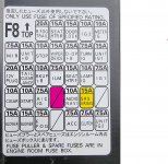
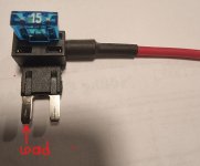
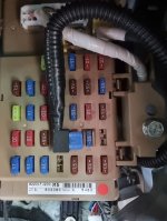
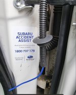
I ended up running the blue wire to the opposite side of the engine bay through the Driver side guard ( Oz - left hand drive so steering wheel on the right), around the firewall and through the 20mm grommet near the door hing to the under Dash fuse box. I installed the fuse tap into No 23 fuse(on my fuse box diagram) which was empty and placed a 15amp fuse in the top of the Dual fuse Tap (as my blue wire size was rated at 10 Amps)leaving the bottom fuse empty. I tested voltage on the Fuse Tap wire with the red probe of the multi-meter while the black probe was pushed against a chassis bolt. The Fuse Tap wire showed no power when UN-fused and live when the Top 15 Amp fuse was installed and ignition turned on. Next I checked the other end of the blue wire connected to the 3 post Anderson plug at the back of the vehicle where the charger is located and it showed around 12.27 volts with the ignition on and 0 volts with the engine off, so all good.

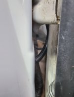
I did not put a fuse into the bottom fuse holder of the Tap as there was none in the fuse box socket to start with. Also good to mention is that one side of the fuse box slot for the tap is live while the other is not. If you put the Fuse Tap in the wrong way your fuse will be by-passed which will still supply power to the wire however it will not be fused so could cause a lot of damage to the vehicle or even a fire so I had to make sure the live fuse box slot connected to the front side fuse Tap blade and the non live slot was located closest to the wire side of the fuse tap. Hence it looks upside down in the photo.
 

Attachments

  • Fuse box lid.jpg
    Fuse box lid.jpg
    376.5 KB · Views: 2
  • Fuse Tap.jpg
    Fuse Tap.jpg
    164 KB · Views: 3
  • Under Dash Fuse Box.jpg
    Under Dash Fuse Box.jpg
    256.8 KB · Views: 3
  • Wire and 20mm Grommet.jpg
    Wire and 20mm Grommet.jpg
    240.8 KB · Views: 3
  • wire around Firewall.jpg
    wire around Firewall.jpg
    179.9 KB · Views: 3
Thanks temmah and Kevin. I actually set the BCDC Charger up in an ABS Case with Anderson plug connections so it is fully transportable. I'll include that in another post as soon as I get a chance. Hopefully starting an install of a Tow-Pro Electric Brake controller this weekend, if it turns up today.
 
Back
Top